What is an antenna tuner
Let’s start with a common complaint: The designation “antenna tuner” is wrong! There is some truth in this, because the antenna itself is not tuned or modified. In fact, nothing changes about the antenna itself. The antenna shows a certain impedance at a certain frequency. The antenna tuner adjusts the impedance of the antenna to the required impedance of the transceiver, which is 50 ohms. So you might better call an antenna tuner an “impedance transformer unit.” Everyone is talking about antenna tuners now, so that’s what we do. There is much debate about the usefulness and efficiency of antenna tuners, reason enough to go into a little more detail here.
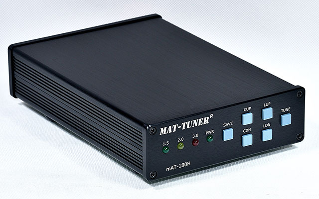
Antenna impedance
The impedance of an antenna can vary greatly depending on the frequency. In many cases, the antenna is intended for only one particular frequency. There are still a variety of factors that affect the impedance of the antenna. Obviously, the type of antenna is important, but also the size of the antenna, the height, the type of soil and interfering elements near the antenna. The required impedance for a modern transceiver is 50 Ohms. The coaxial cables used are also based on 50 Ohms. If antenna and coaxial cable are both 50 Ohms, the SWR meter reads cleanly 1:1.
But what if the antenna shows an impedance of 100 ohms? Because the coaxial cable is made for an impedance of 50 ohms, an impedance transformation also takes place here. This depends on the length of the coaxial cable. In this article, we will leave this phenomenon aside for the moment. If you want to know more about this look here. The transceiver would like to see 50 Ohms but the impedance is 100 Ohms, now what? Or even a bit more complex, there is also an inductive or capacitive component added to the impedance. In this case, the antenna tuner comes into play.
When to use an antenna tuner
This depends enormously on the antenna situation. Let’s cover some of them:
Dipole antenna
A coax fed dipole antenna with a BalUn in the feed point does not need an antenna tuner in many cases. This is because the antenna shows an impedance of about 50 Ohms. If this is not the case, then it is more a matter of adjusting the antenna length. An antenna tuner can be useful, however, to get the ends of the band (i.e., low or high in the band) neatly 1:1 with the dipole antenna. Especially on 80 meters, you do not succeed in getting the dipole broadbanded to the point where the entire band shows an acceptable SWR.
For coax fed dipole antennas, use an antenna tuner only on the band the antenna is intended for. So don’t go tuning a coax-fed dipole antenna of 2x 10 meters for the 40 meter band on 20 meters. Possibly the tuner will get it done but the efficiency will be dramatic.
Multi band antennas
Multiband antennas fed with coaxial cable such as the G5RV, ZS6BKW, Multiband EndFed, FD3, FD4, (Windom antenna) etc. tend to have perfect impedance on some bands and slightly off on others. This depends, for example, on the antenna height, soil type and objects near the antenna. An antenna tuner can then help to still be able to use the antenna on all intended bands. Do not try to tune bands that the antenna is not made for, this will cause large losses in the coaxial cable.
Vertical antennas
Vertical quarter-wave antennas placed on the ground with a radial network are in some cases shortened with a coil (think vetical for 80 meters). An antenna electrically shortened by means of a coil has a limited bandwidth. In this situation, the tuner can also help. In this case, do use a common mode choke at the feed point so that the coaxial cable does not inadvertently act as a radial.
Longwire antenna
The term “longwire antenna” often refers to any length of wire fed at the end (or beginning), In many cases a 1:9 UnUn is used at the feed point. From the 1:9 UnUn one continues with coaxial cable to the tuner. This system can work nicely in practice but is far from ideal. This is because the coaxial cable acts as a counter capacity and unintentionally radiates with it. A common mode choke and some counter-capacity is recommended.
A better alternative to this system is an antenna tuner placed directly at the feed point of the wire. Thus, the impedance of the wire directly at the tuner is converted to 50 ohms and no more losses occur in the coaxial cable due to a huge mismatch. The length of the wire determines which bands can be worked on, Avoid half wavelengths of wire or multiples thereof, then the impedance is very high and thus troublesome for the tuner.
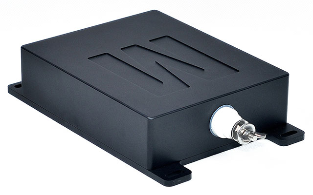
mAT-40 Automatic antenna tuner, weatherproof, for placement directly at the feed point of a long-wire antenna.
Doublet antenna
The doublet antenna is a symmetrical open dipole antenna fed by a symmetrical feed line. These antennas come in all shapes and sizes and are widely used. If this antenna system is connected to a symmetrical antenna tuner, virtually any band can be worked on. Of course, this does depend on the antenna length, feed line length and the capacity of the antenna tuner. It is also possible to apply a Doublet antenna in combination with an asymmetrical tuner, more on that below….
Symmetrical antennas and feed line
Most automatic antenna tuners are asymmetrical, so suitable for tuning coax-fed antennas. As mentioned earlier, I am not a fan of tuning coax fed antennas with very poor SWR. There is then a lot of loss in the coaxial cable, the BalUn possibly present in the feed point of the antenna is often not suitable to handle impedance other than around 50 Ohm.
To reduce losses, it is a better idea to keep the antenna and feed line symmetrical, so fed with ribbon line or open line. How to use a symmetrical antenna and feed line in conjunction with an asymmetrical (coax) antenna tuner.
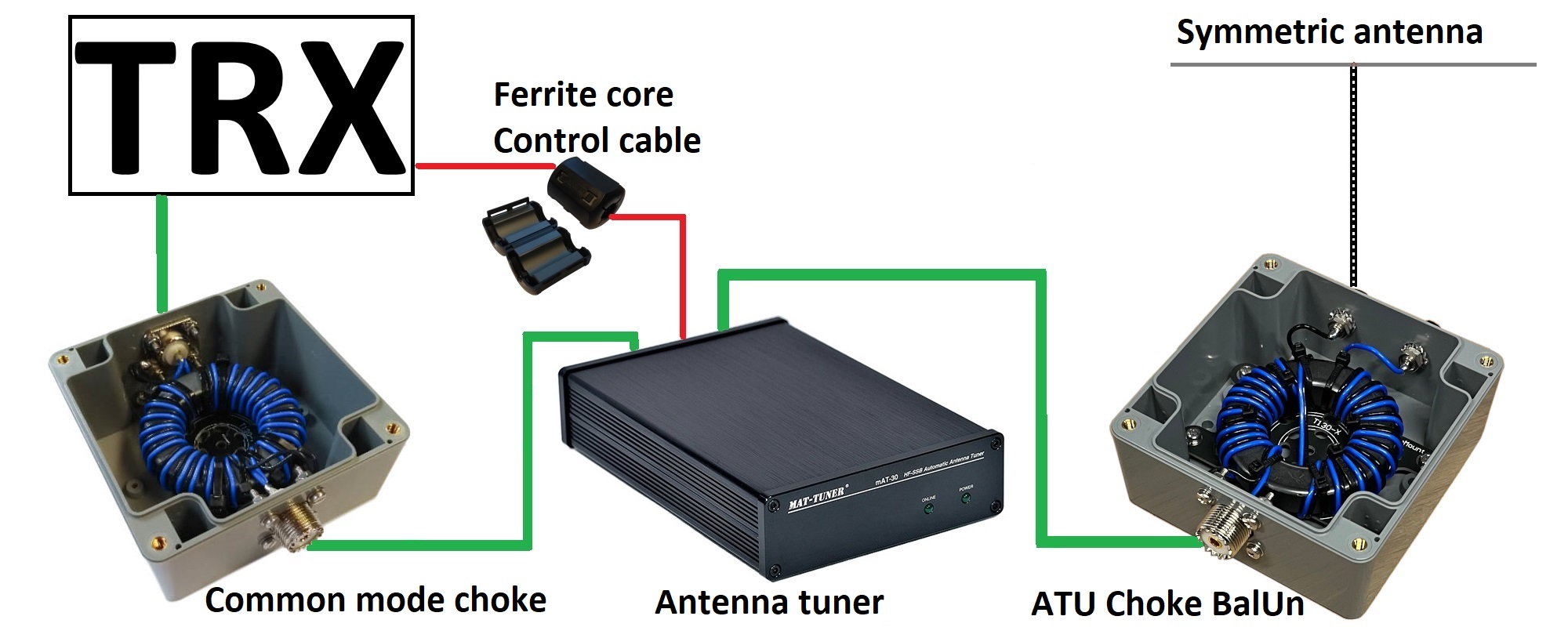
The image above shows how an asymmetrical tuner is used with a symmetrical antenna and feed line system. Immediately after the antenna tuner is placed an ATU Choke BalUn suitable for a variety of impedances. So do not place a standard 1:1 BalUn here, this type of BalUn is designed for 50 Ohm and not suitable for this application. This ATU choke BalUn forces the currents in the symmetrical supply line to be equal to each other. As a result, the feed line does not radiate with it. Make the coaxial cable between the antenna tuner and the ATU choke BalUn as short as possible.
Some measures between the transceiver and antenna tuner were also taken. A common mode choke filter is included in the coaxial cable so that the antenna tuner will not use the input coaxial cable (and anything attached to it) as an unintended counter-capacity. Winding the coaxial cable several times through a ferrite core is also a solution. Also provide the control cable from the transceiver and any DC power cable with the necessary ferrite material. Again, to prevent unintended countercapacity.
How a tuner works
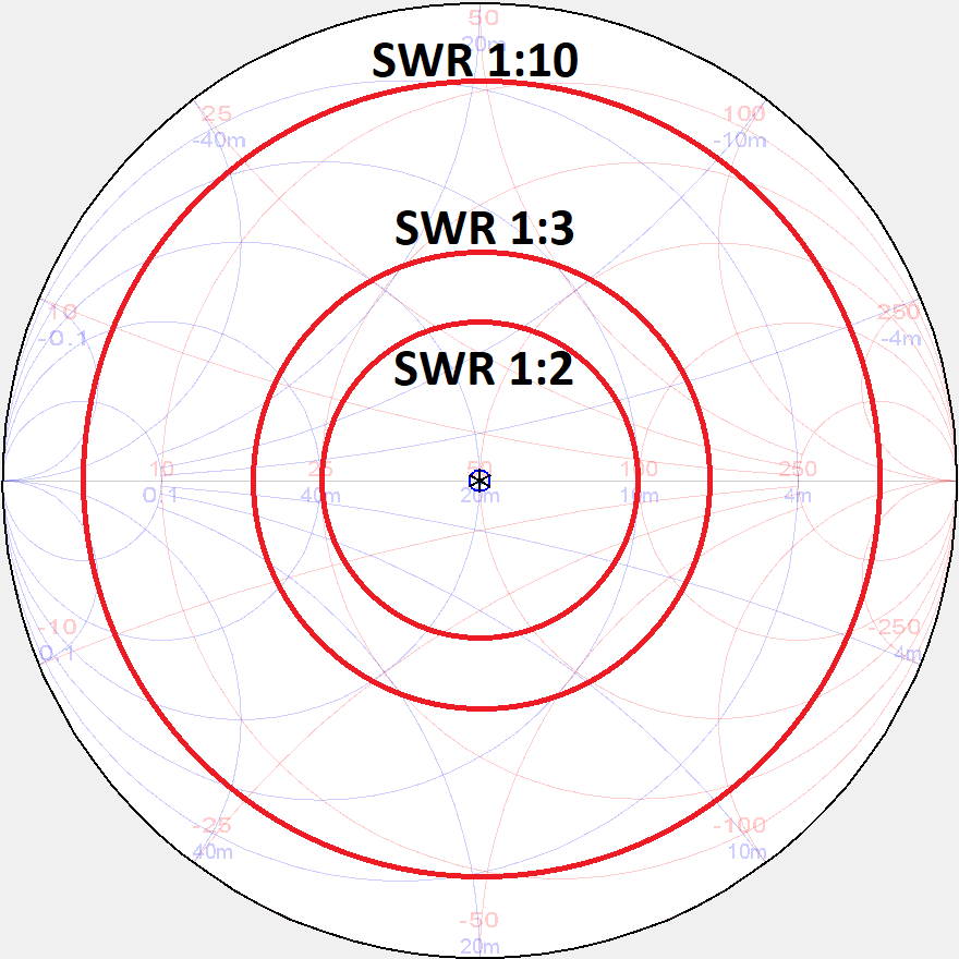
The lower left image shows a Smith chart with three red circles. The circles indicate an SWR of 1:2, 1:3 and 1:10. The closer to the center of the chart, the better the SWR. The more outward, the worse the SWR. If you connects a VNA to the antenna, you can nicely see where the resonance point is on the Smith card. The the lower right image shows an antenna impedance of 100 + 100j. This implies a real component of 100 Ohms and a complex component of 100 Ohms. By applying a coil and capacitor in the antenna tuner in a certain way, the impedance can be transformed to 50 ohms.
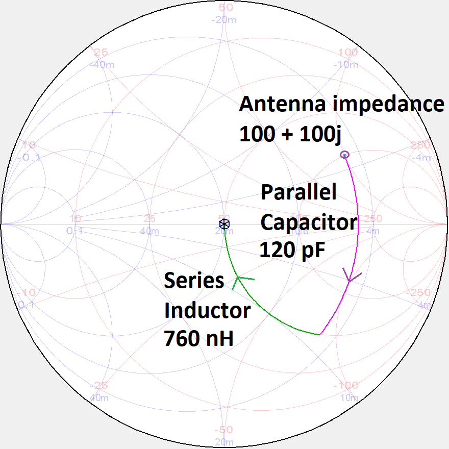
The image below shows what the schematic of the tuner looks like. In practice, the worse the SWR (more to the outside of the Smith chart) the larger the coil and capacitor in the tuner should be. This also depends on the frequency. For the 160 meter band, large coils and capacitors are soon used. There is a nice simulation program available to experiment with this: SimNEC

Manual or automatic tuner
This depends entirely on your personal preference. An automatic antenna tuner obviously gives great ease of operation and is often easily controlled from the transceiver. During tuning, the transceiver outputs a signal with limited power while the automatic tuner searches for the best combination of coil and capacitor. An automatic antenna tuner can only tune with limited power otherwise the tuner will be damaged.
A manual tuner (air capacitor and coil) can often handle a lot of power during tuning. Manual tuners are fun to build but if you are a “band hopper,” you will keep turning by hand all the time. Unfortunately, roller coils and large air capacitors are hard to find these days and quite pricey.
Internal or external tuner?
An internal antenna tuner in the transceiver is sometimes sufficient. Such a tuner is made for adjusting relatively minor misadjustments. An external tuner is soon needed if the misadjustment exceeds about 1:3 (SWR). If an amplifier is used you can not use the internal tuner because the tuner is placed after the amplifier.
What do I need to pay attention to?
- The tuner must be able to handle sufficient power
- Note: PEP power is often listed. Also note Digimodes, FM, RTTY, FT8, etc.
- Make sure your automatic antenna tuner can be controlled from the transceiver.
- If using an amplifier, make sure the tuner automatically interrupts the PTT line to the amplifier when tuning.
Our offerings:
| mAT-30 | mAT-Y200 | mAT-K100 | mAT-M200 | mAT-180H | mAT-125E | mAT-1500pro | mAT-40 | mAT-705 | |
|---|---|---|---|---|---|---|---|---|---|
| Max PEP vermogen | 120 Watt | 200 Watt | 120 Watt | 200 Watt | 120 Watt | 120 Watt | 1500 Watt | 120 Watt | 10 Watt |
| Max Continu vermogen | 30 Watt | 100 Watt | 30 Watt | 100 Watt | 30 Watt | 30 Watt | 800 Watt | 30 Watt | 10 Watt |
| Handmatig gebruik | ja | ja | ja | ||||||
| Yaesu aansturing | ja | ja | ja | ja | |||||
| Icom aansturing | ja | ja | ja | ja | ja | IC-705 | |||
| Kenwood aansturing | ja | ja | ja | ja | ja | ||||
| LED SWR aanduiding | ja | ja | |||||||
| Handmatig fine-tuning | ja | ja | |||||||
| Geschikt voor Eindtrap | ja | ||||||||
| Gevoed door accu | ja | ja | |||||||
| RF IN | SO-239 | SO-239 | SO-239 | SO-239 | SO-239 | SO-239 | SO-239 | SO-239 | BNC |
| RF OUT | SO-239 | SO-239 | SO-239 | SO-239 | SO-239 | SO-239 | SO-239 | Long-wire | BNC |
| Geschikt voor buiten | ja |


